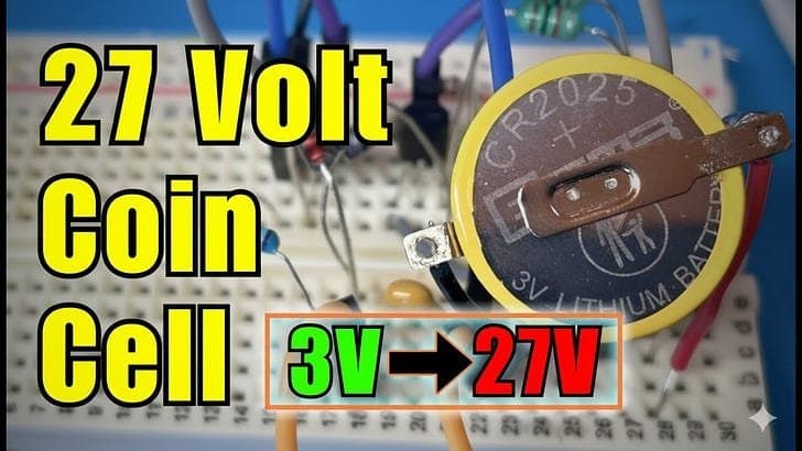
A broken bistable LCD display PCB sparks a deep dive into the Joule thief circuit, where a simple setup transforms a 3V coin cell into a 27V power source. Through iterative experimentation, the circuit achieves remarkable efficiency, drawing minimal current and enabling thousands of operations, showcasing its potential for low-energy devices.
When Chris Greening accidentally destroyed a bistable LCD display PCB—a device reliant on a mysterious 27V boost from a humble coin cell—it ignited a quest to resurrect its functionality. This mishap led to an exploration of the Joule thief circuit, a clever piece of electronics folklore that defies intuition by stepping up voltage with minimal components. The journey not only demystifies high-voltage generation but also reveals optimizations that could inspire low-power innovations in IoT and wearable tech.
The Broken Board and the Mystery IC
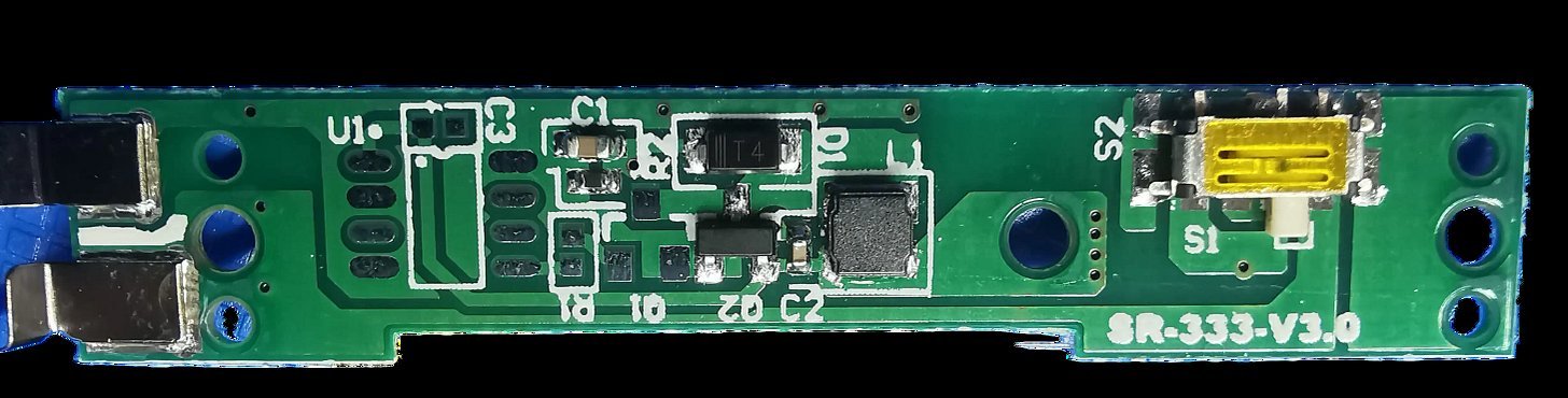 The original PCB, now lifeless after an experiment gone awry, housed an unknown integrated circuit (IC) that efficiently converted 3V from a coin cell to 27V. This voltage is essential for clearing bistable LCDs, which retain images without power. With the IC unidentified, Greening turned to a classic alternative: the Joule thief circuit. Named for its ability to 'steal' every last joule of energy from batteries, this oscillator-based design has been a staple of DIY electronics for years, though it's rarely documented with such rigor for modern applications.
Building the Basic Joule Thief
At its core, the Joule thief relies on a transistor, inductor, and resistor to create a self-oscillating boost converter. Greening’s initial breadboard setup used two 1mH inductors instead of a hand-wound coil, simplifying construction. The circuit included a 10kΩ base resistor (higher than typical for reduced current draw) and a series resistor to protect the battery:
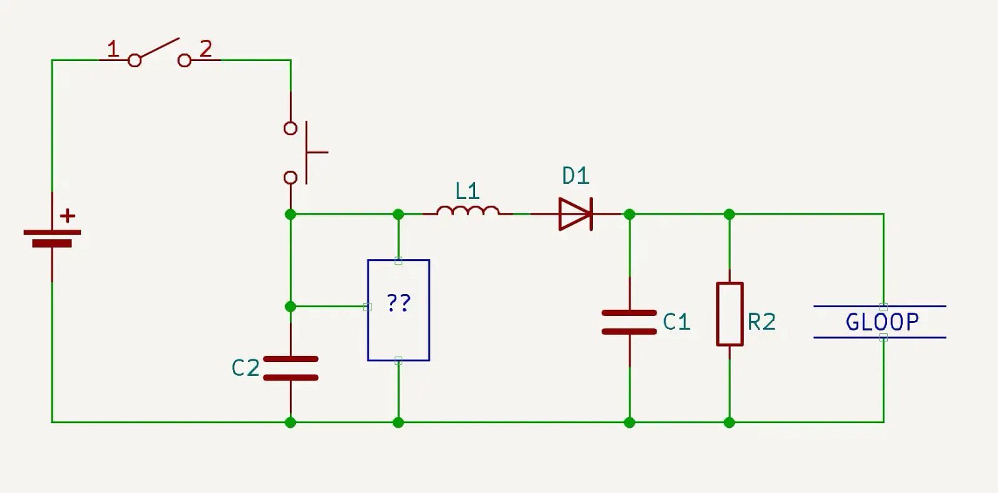
Simple Joule Thief Circuit:
- Battery (3V coin cell) → Series Resistor
- Transistor Base → 10kΩ Resistor
- Inductors in feedback loop
- Output: 27V Zener diode, capacitor, and 1MΩ bleed resistor
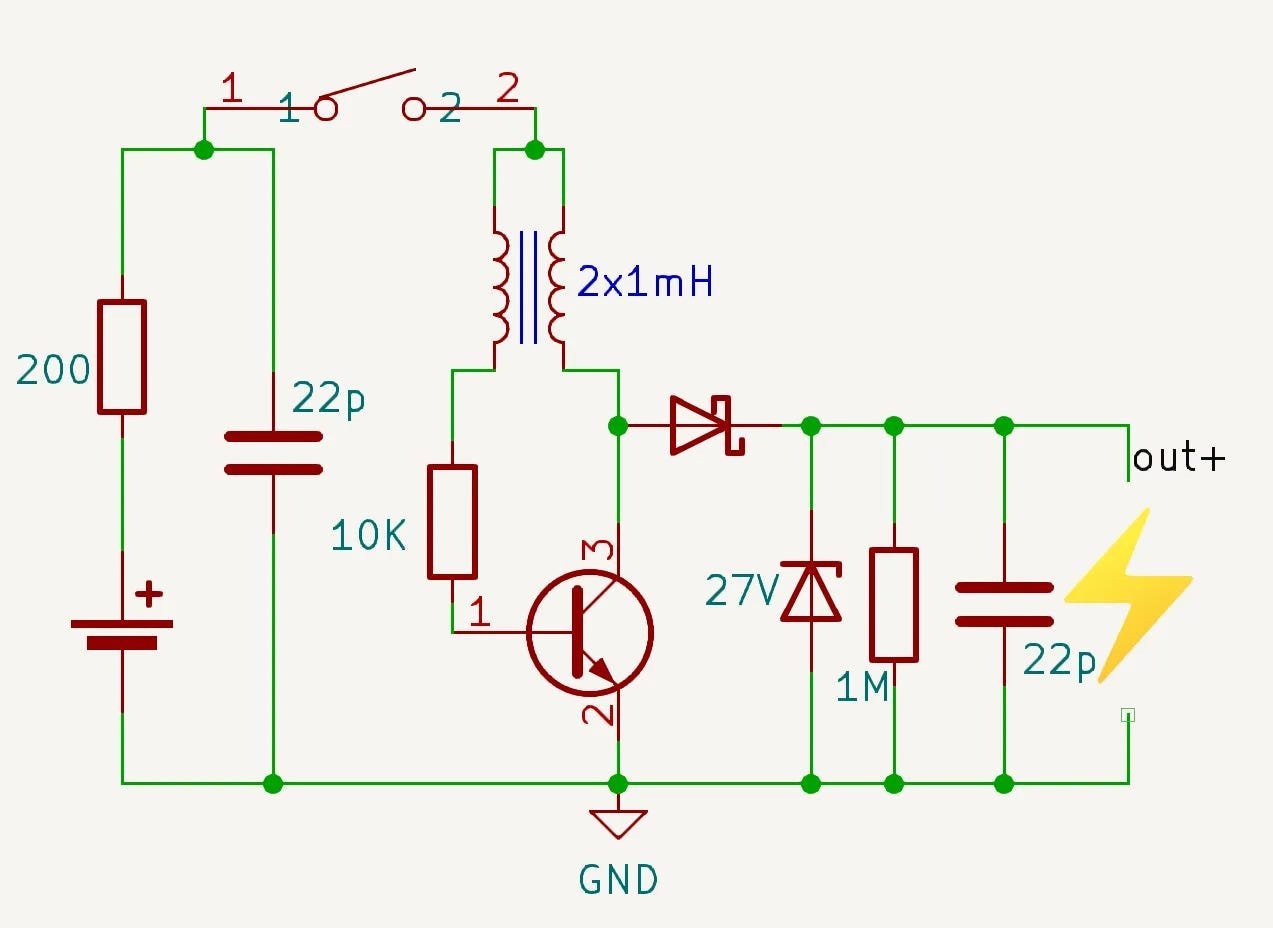 Surprisingly, this basic design delivered the needed 27V effortlessly. Power monitoring revealed a 10mA current draw during operation—manageable for a coin cell if used sparingly. ChatGPT estimated 40,000–50,000 button presses per cell, highlighting the circuit’s suitability for intermittent tasks like display resets.
Optimizing for Efficiency
To minimize power waste, Greening evolved the design into a regulated Joule thief. Adding a second transistor created a feedback loop that cuts power once the target voltage is reached. This version slashed average current draw to just 1.53mA, as shown in the power profile:
Regulated Joule Thief Circuit:
- Adds a second transistor for feedback
- Halts oscillation at 27V, eliminating idle current
- Ideal for applications with no sustained load
 The regulated circuit’s current profile showed a brief 10mA spike followed by a near-instant drop to near zero, making it vastly more efficient. This refinement underscores how minor tweaks can yield outsized gains in energy-constrained environments, from disposable sensors to backup systems.
Why This Matters for Engineers
Joule thief circuits exemplify elegant, low-cost solutions to voltage-boosting challenges, especially where space and power are limited. Greening’s experimentation—detailed in his full video—demonstrates that even 'old' tech like this remains relevant. For developers working on ultra-low-power devices, such circuits offer a blueprint for extending battery life without complex ICs. As energy harvesting gains traction, revisiting these fundamentals could unlock new efficiencies in sustainable tech.
Source: Adapted from Chris Greening's original article on atomic14.substack.com.
Comments
Please log in or register to join the discussion