The race to build commercially viable humanoid robots is driving a fundamental rethinking of actuator design, with companies like Tesla, Figure, and Agility developing custom solutions that solve the physics of walking, thermal management, and human interaction.
The humanoid robotics race has reached a critical inflection point. While companies like Boston Dynamics have captivated the world with dramatic demonstrations, the real commercial viability of these machines hinges on a less visible but far more critical component: the actuators that power their movements. The difference between a laboratory curiosity and a commercially successful humanoid robot often comes down to how well these machines solve the fundamental physics challenges of bipedal locomotion.
The Walking Problem: Why Current Actuators Break
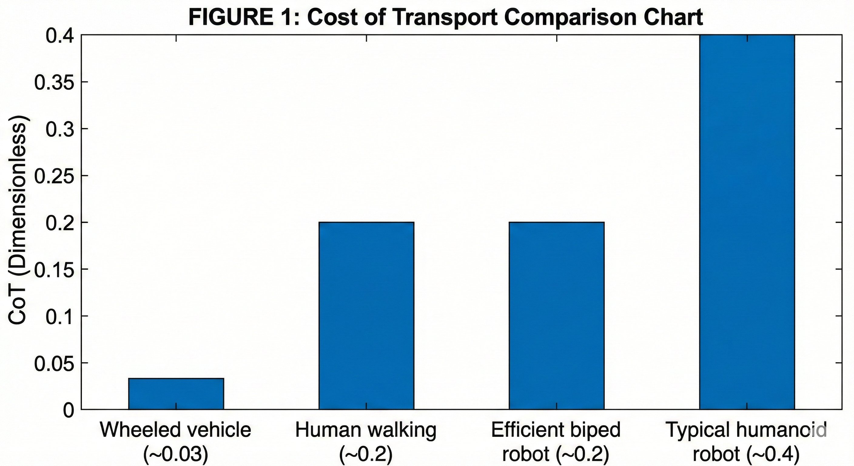
A humanoid robot takes roughly 5,000 steps per hour. Each step sends a shock of 2-3× body weight through the leg actuators—forces that would be fine occasionally, but become destructive when repeated thousands of times without pause. This relentless duty cycle is why most actuators fail in humanoids, and why the survivors all converged on similar engineering solutions.
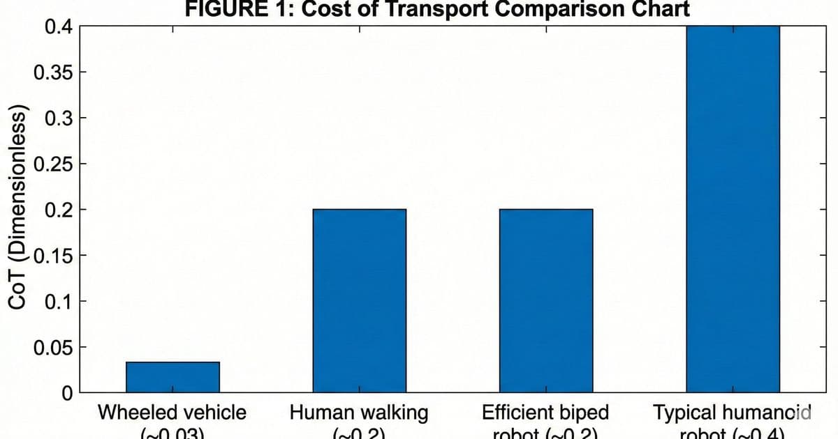
The Cost of Transport (CoT) metric reveals the fundamental challenge: wheeled vehicles achieve CoT values of 0.01-0.05, while bipedal robots typically land between 0.2 and 0.5—that's 10 to 50 times worse. For actuator design, this means every gram of mass directly increases the energy cost of movement.
The Math of Fatigue When we state that a humanoid takes roughly 5,000 steps per hour, this isn't a theoretical maximum—it's a baseline for commercial viability. A warehouse robot targets a sustained pace of approximately 1.4 steps per second (84 steps per minute) to balance speed with stability. Over a single 8-hour shift, this accumulates to over 40,000 load cycles. In just one month of operation, a humanoid leg endures roughly one million cycles—a fatigue timeline that compresses years of standard industrial wear into weeks.
Static Force vs. Dynamic Impact There's a critical difference between lifting a weight and catching a falling weight. Industrial actuators are typically rated for static or quasi-static loads—slowly applied forces with plenty of time for the mechanical system to distribute stress. Walking is nothing like this.
During the heel strike phase of gait, a 70kg humanoid experiences 1,400-2,100N of force applied in approximately 50-100 milliseconds. A ball screw rated for 5,000N of static load will often fail catastrophically when subjected to repeated 2,000N dynamic impacts because the internal ball bearings can brinell (dent) the raceways under the shock load.
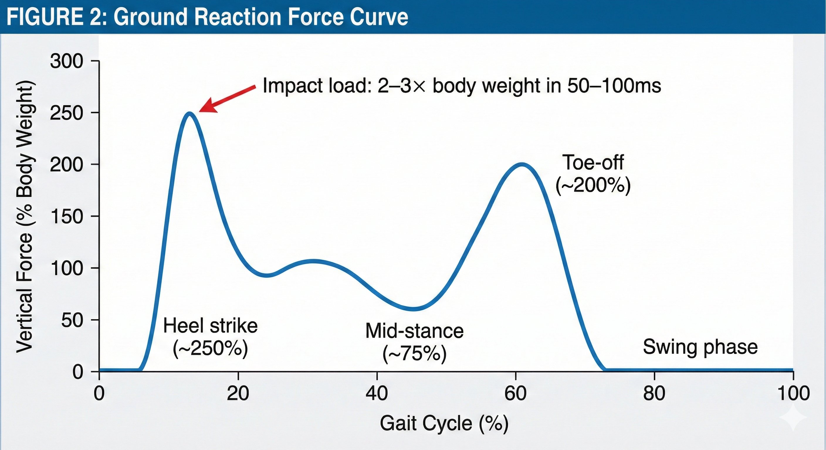
Torque vs. Force: The Architecture Decision For the major joints of a humanoid—hips, knees, ankles, shoulders, elbows—rotary actuators dominate. These typically combine a brushless motor using rare earth magnets for high-powered rotary output. The critical metric here is torque density (Nm/kg), and the design challenge centers on managing reflected inertia and maintaining back-drivability through the gear train.
Linear actuators serve a different role—smaller, secondary movements where compact packaging matters more than high torque. Finger actuation is the clearest example: micro linear actuators can fit within the forearm to drive tendons or linkages to each finger.
The True Metric: Specific Torque and Specific Force Given the mass penalty, the critical performance metric for humanoid actuators is output per unit mass. For rotary actuators driving major joints, this is Specific Torque (Nm/kg). For linear actuators in secondary applications, it is Specific Force (N/kg).
For a humanoid leg actuator to be viable, specific torque typically needs to exceed 10 Nm/kg, while specific force for linear actuators should exceed 4,000 N/kg. Most industrial actuators fall well short of these thresholds—immediately disqualifying them from serious consideration.
The Mass Penalty Spiral When an actuator is too heavy, the robot doesn't just carry extra weight. It enters a compounding cycle that amplifies the original problem. This isn't a linear relationship; it is exponential.
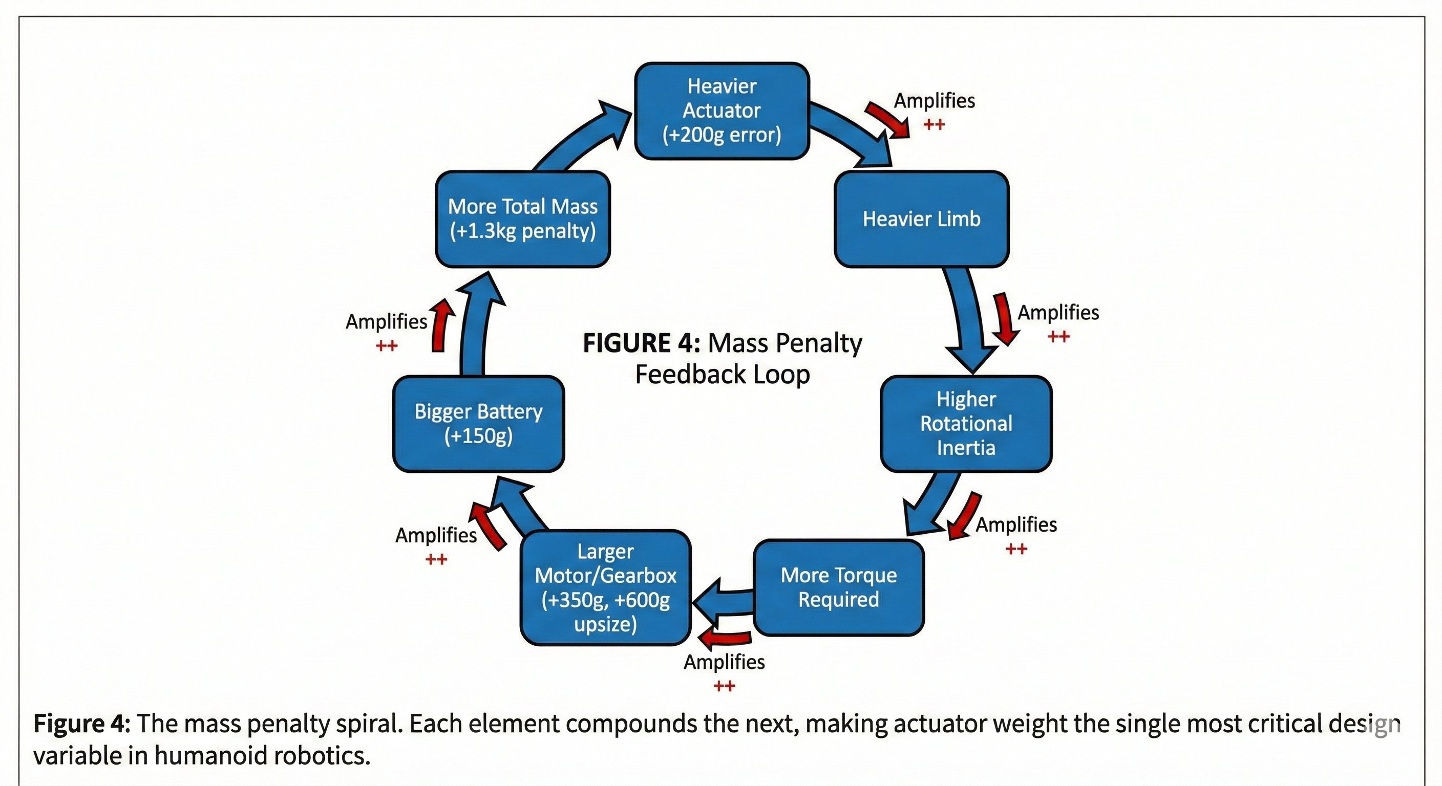
Consider a designer who chooses a cheaper, heavier actuator that is 200g overweight for the ankle joint:
- Step 1 (Ankle): +200g added to the foot
- Step 2 (Knee): The knee actuator must now lift that 200g at the end of a lever arm (the shin). To handle this increased torque, the knee actuator must be upsized by +350g
- Step 3 (Hip): The hip actuator now lifts the heavier foot (+200g) AND the heavier knee (+350g). It must be upsized by +600g
- Step 4 (Battery): To power these larger motors, the battery pack grows by +150g
Result: A 200g error at the component level became a 1.3kg penalty at the system level. The robot is now slower, less efficient, and more prone to impact damage.
How the Penalty Differs: Rotary vs. Linear
- Rotary Actuators (The "Reflected Inertia" Trap) For rotary actuators at major joints, mass kills performance through Reflected Inertia. This is the resistance the joint feels when an external force (like the ground) tries to move it. The formula for Reflected Motor Inertia at the output is:
Joutput = Jrotor × (Gear Ratio)²
Note the square. A 100:1 gearbox doesn't just multiply torque by 100; it multiplies the motor's own inertia as seen by the output by 10,000. This means when the robot's foot hits the ground, the ground tries to back-drive the motor. With a high gear ratio, the leg "feels" the motor's spinning rotor as being 10,000 times heavier than it actually is.
This is why modern humanoids strive for Quasi-Direct Drive (QDD) actuators with low gear ratios (6:1 to 30:1) rather than high-ratio industrial gearboxes.
- Linear Actuators (The "Mass Distribution" Trap) For linear actuators used in secondary applications, the penalty is about mass distribution rather than reflected inertia. A heavy linear actuator placed in the forearm to drive finger tendons shifts the arm's centre of mass distally (towards the hand). Every gram added to the forearm is amplified by the full length of the arm acting as a lever—the shoulder and elbow rotary actuators must now produce more torque just to move the arm.
The principle of Proximal Actuation applies here: mount heavy components as close to the body's centre as possible. A heavy actuator in the torso is manageable; a heavy actuator in the hand is a disaster.
The Convergent Solution: The Split Architecture When companies like Tesla, Figure, and Apptronik focused on building high-payload general-purpose humanoids, they independently arrived at the same actuator architecture. The constraints of human-like strength and endurance force designers toward a strategic split: rotary actuators for joints that primarily spin, and linear actuators for joints that must absorb heavy shock loads and lift significant weight.
Inside the Rotary Actuator: Strain Wave Gearing For joints that primarily rotate—shoulders, wrists, hip rotation—modern rotary actuators are built around Strain Wave Gearing (often called by the brand name "Harmonic Drive") paired with high-density frameless motors. Unlike standard gears that rely on rigid teeth meshing with rigid teeth, a Strain Wave Gear relies on the elastic deformation (flexing) of metal to transmit motion.
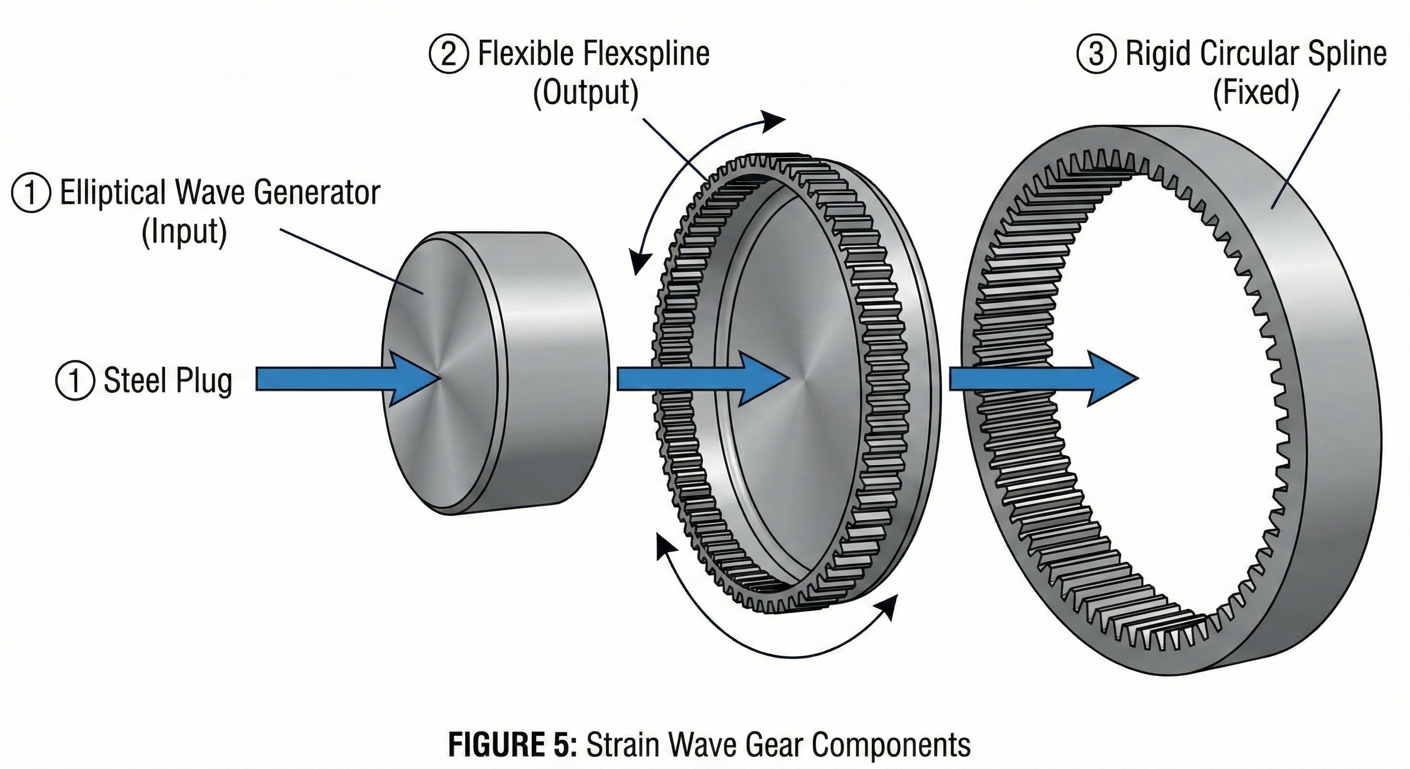
A Strain Wave Gear consists of only three parts:
- The Wave Generator (Input): An elliptical (oval-shaped) plug connected to the motor shaft
- The Flexspline (Output): A thin, flexible metal cup with teeth on the outer rim
- The Circular Spline (Fixed): A rigid outer ring with teeth on the inside
The Wave Generator pushes the flexible Flexspline outward, forcing its teeth to mesh with the outer Circular Spline at the two long ends of the oval. As the Wave Generator spins, the "wave" of engagement travels around the circumference. Because the Flexspline has fewer teeth than the outer ring, it does not complete a full rotation for every turn of the input.
Why Humanoids Use Strain Wave Gears:
- Zero Backlash: In normal gears, there is a tiny gap between teeth (slop). In a Strain Wave Gear, the flexible metal is pre-loaded tight against the outer ring, creating zero play.
- High Torque Density: It produces enormous turning force relative to its small size and weight—critical for keeping limb mass low.
- Single-Stage Reduction: It achieves high gear ratios in a single stage, keeping the actuator flat and compact like a hockey puck.
Inside the Linear Actuator: Planetary Roller Screws For joints that must absorb heavy shock loads—knees, elbows, ankles—humanoids designed for payload use linear actuators built around Planetary Roller Screws. These actuators push and pull (linear output) rather than spin, similar to how your quadriceps muscle extends your knee.
Inside a linear actuator:
- Frameless torque motor: The stator remains fixed while the rotor spins the nut
- Inverted Planetary Roller Screw: Threaded rollers orbit inside the spinning nut. As the nut rotates, the central screw shaft is forced to extend or retract linearly
The result is a cylindrical tube (often gold-anodized on Tesla prototypes) with the screw shaft extending from one end. The motor housing stays stationary while the shaft moves.
Why Roller Screws Instead of Ball Screws? Ball screws are ubiquitous in industrial machinery—CNC machines, injection moulding, precision positioning systems. Why don't humanoids use them? The answer is contact geometry and how it responds to shock loads.
Ball screws use spherical balls rolling in grooves. Each ball makes point contact with the raceway—a tiny contact patch that concentrates Hertzian stress. Roller screws use threaded rollers that make line contact along their length. This distributes the load across a much larger surface area—typically 10–15× more contact area than a ball screw of equivalent size.
The Brinelling Problem When a humanoid's foot strikes the ground, that impact travels up through the ankle and knee actuators. This is a shock load—a sudden spike of force far exceeding static ratings. In a ball screw under shock load, the point contact between each ball and the raceway experiences extreme Hertzian stress. If this stress exceeds the material's yield strength, the ball creates a tiny permanent dent in the raceway. This is called Brinelling.
One dent is imperceptible. But a humanoid takes 5,000 steps per hour. Each step adds more microscopic damage. Over days or weeks, the raceway becomes rough, backlash increases, efficiency drops, and eventually the screw fails completely.
Roller screws survive because line contact keeps peak Hertzian stress below the yield threshold, even under repeated impact loading. The same shock load that destroys a ball screw in weeks can be absorbed by a roller screw for years.
The Gear Reduction Trade-off The fundamental tragedy of robotics is that electric motors and biological limbs want opposite things. A highly efficient electric motor is most comfortable spinning at 3,000+ RPM with low torque. A human knee walking up stairs operates at roughly 30 RPM with massive torque. To bridge this 100× gap, engineers use gear reduction.
But gearing is not a free lunch. It introduces a penalty that scales not linearly, but exponentially: Reflected Inertia.
The N² Trap: Reflected Inertia If you put a 100:1 gearbox (N=100) on a motor, you multiply the output torque by 100. That's the good news. The bad news is that the inertia—the resistance to changing speed—is multiplied by the square of the gear ratio (N²).
Jreflected = Jmotor × N²
For a 100:1 gearbox, the motor's own inertia feels 10,000 times heavier to the output shaft. When a robot's foot hits an unexpected obstacle—a rock, a step edge, a cable on the floor—the leg needs to yield instantly to absorb the shock. If the gear ratio is too high, the motor's reflected inertia is so massive that the leg cannot accelerate out of the way fast enough. The leg acts like a solid steel rod rather than a springy muscle.
Two Competing Approaches
- Quasi-Direct Drive (QDD) — The "Cheetah" Approach Used by: Unitree (H1, G1), MIT Mini Cheetah, dynamic jumping robots.
Strategy: Use a large, pancake-shaped motor with very low gearing (6:1 to 10:1).
The Benefit: The robot is naturally "bouncy." You can grab the limbs and move them freely—the motor spins with minimal resistance. The robot can detect ground contact purely by monitoring motor current, with no need for expensive force sensors. Impacts are absorbed because the low reflected inertia allows rapid acceleration.
The Trade-off: The motor must be physically large and heavy to produce sufficient torque, since gearing provides little mechanical advantage. It consumes massive current to hold static poses (like standing still or holding a box), generating significant heat.
- High-Reduction Actuators — The "Lifter" Approach Used by: Tesla Optimus, Figure, Apptronik Apollo, industrial humanoids.
Strategy: Use a smaller, faster motor with high gearing (50:1 to 160:1), such as Strain Wave Gears (Harmonic Drives) or Planetary Roller Screws.
The Benefit: Massive strength in a compact, lightweight package. The robot can lift heavy boxes, climb stairs with payloads, and hold positions without overheating the motor windings. Less current is needed to maintain static poses.
The Trade-off: The actuator is mechanically "opaque." The motor cannot feel forces from the environment through the friction and inertia of the gears. To achieve compliance, these robots require dedicated torque sensors (strain gauges) on the output shaft, plus sophisticated software to simulate the springy feel that QDD robots get for free.
The Sweet Spot Designers are constantly hunting for the "golden ratio"—usually between 30:1 and 50:1 for general-purpose humanoids—where the actuator is strong enough to lift a payload but transparent enough to walk safely.
Backdrivability: The Safety Test A simple test reveals where an actuator sits on this spectrum: can you grab the robot's hand and move it?
High Gear Ratio: No. The joint feels locked. Without power, the robot holds its position. The system requires force sensors to detect your touch.
Low Gear Ratio: Yes. The joint moves freely. The motor spins backward as you push. The robot inherently "knows" you're there because it feels the current change.
This distinction matters enormously for safety. A backdrivable robot that trips will crumple and absorb the fall. A non-backdrivable robot that trips will slam into the ground (or a nearby human) like a falling statue.
Thermal Reality Inside a Robot Leg While gearing and inertia define how a robot moves, thermodynamics defines how long it can work. The dirty secret of humanoid robotics specifications is the massive gap between "Peak Torque" and "Continuous Torque."
A robot might be rated to lift 50kg, but thermally, it might only sustain that load for 15 seconds before its actuators cook themselves. This isn't a minor engineering detail—it's the factor that separates laboratory demonstrations from commercial products.
The "Zero RPM" Problem When you lock your knees to stand, your bones support your weight. Your muscles do minimal work. Your metabolic cost is near zero.
When a robot bends its knees to stand, the motor must constantly fight gravity. There is no skeletal structure to lock against. To an electric motor, holding a static load—known as stall torque—is the most punishing state possible. The motor pushes current (I) through copper windings to generate magnetic force. Even though the motor isn't spinning, that current encounters electrical resistance (R). The energy has nowhere to go but into heat, following the Joule Heating law:
Pheat = I² × R
Because heat scales with the square of the current, a 2× increase in load results in a 4× increase in heat generation. In a deep squat—the pose a humanoid takes to pick up a box from the floor—the knee actuators act less like motors and more like toaster ovens. They're generating maximum heat while doing zero mechanical work.
The Thermal Cliff: Peak vs. Continuous Torque This physics creates what engineers call the Thermal Cliff—the stark divide between what an actuator can do briefly and what it can do indefinitely.
The Two Torque Ratings:
- Peak Torque: The maximum force the motor can exert before the magnetic field saturates. This is the number in marketing materials. It can only be sustained for seconds.
- Continuous Torque: The maximum force the motor can sustain indefinitely without melting the winding insulation or demagnetising the permanent magnets. This is the engineering reality.
In typical air-cooled actuators, Continuous Torque is only 25–30% of Peak Torque. Consider the implications: if a robot needs 100 Nm of torque to stand up from a squat (Peak), but can only sustain 30 Nm continuously, it will inevitably overheat simply by existing in gravity.
Closing the Gap: Liquid Cooling This thermal bottleneck is why Tesla, Figure, and other manufacturers developing commercial humanoids are moving toward liquid-cooled actuators. By pumping dielectric oil or water-glycol mixture through channels machined into the motor housing—and in some designs, directly over the stator windings—engineers can remove heat 10× faster than air convection alone.
This "vascular system" allows the motor to operate at much higher continuous currents, raising the Continuous Torque rating from 25–30% of Peak to potentially 60–70% of Peak.
Control Architecture: From PWM to Torque Control If you take a standard industrial robot arm and push it, it feels like a brick wall. The arm is rigidly locking its joints to maintain a specific coordinate in space. This is Position Control, and it is arguably the single biggest obstacle to creating a useful humanoid robot.
To survive in the real world—walking on uneven terrain, absorbing impacts, interacting safely with humans—a robot must be "compliant." It must yield to unexpected forces and adapt in real-time. Achieving this requires abandoning simple position commands and entering the far more complex world of Torque Control.
The Motor's Operating System: Field Oriented Control (FOC) In cheap hobby servos, the controller sends a "dumb" voltage pulse (PWM) to spin the motor. The pulse width determines average voltage, which roughly determines speed. The controller has no idea how much force the motor is actually producing.
Modern humanoid actuators use Field Oriented Control (FOC)—a mathematical framework that runs directly on the motor driver chip, executing 20,000 times per second. FOC decomposes chaotic AC current into controllable vectors (d-axis and q-axis), allowing precise torque regulation.
Virtual Muscles: Impedance Control Humans don't consciously control the angle of our joints. We control muscle tension—how stiff or relaxed our limbs feel. When you catch a ball, you don't calculate the exact angle your elbow should be; you soften your arm to absorb the impact.
Robots can simulate this using Impedance Control. Since the robot doesn't have actual tendons, it creates "virtual springs" in software. The controller runs a physics equation in real-time:
τ = K(qdes − q) + D(q̇des − q̇)
Where:
- τ = Torque command sent to the motor
- K = Stiffness (how hard the joint resists displacement)
- D = Damping (how much the joint resists velocity—like moving through water)
- qdes = Desired position
- q = Actual position
- q̇ = Velocity (the dot notation indicates rate of change)
The Magic of Variable Stiffness The power of impedance control lies in adjusting K and D on the fly:
- High K (stiff): The joint resists movement strongly. Use this when the foot contacts the ground and needs to support body weight.
- Low K (soft): The joint yields easily to external forces. Use this when swinging the leg through the air, or when absorbing an unexpected impact.
- High D (damped): Movements are slow and controlled, like moving through honey. Good for precise placement.
- Low D (undamped): Movements are quick and bouncy. Good for fast walking or running.
By modulating these parameters hundreds of times per second, a humanoid can make its leg rock-hard when planting its foot, then instantly soft to absorb a stumble.
The Time Machine: Model Predictive Control (MPC) Reaction is not enough. If a robot waits until it starts falling to correct itself, it's already too late. By the time the sensors detect the fall, process the data, and command a correction, the Centre of Mass has moved past the point of recovery.
State-of-the-art humanoids solve this with Model Predictive Control (MPC). This algorithm doesn't just respond to the current state—it runs a physics simulation to predict the robot's state 10-20 timesteps into the future. The controller continuously asks: "If I apply 5 Nm of torque to the ankle now, where will my Centre of Mass be in 500 milliseconds?" It then solves an optimisation problem: find the sequence of torques across all joints that keeps the predicted Centre of Mass within the support polygon (the area bounded by the feet) over the entire prediction horizon.
Compliance and Series Elasticity: The Physics of "Giving In" Catch a cricket ball with a stiff arm and it hurts. Catch the same ball while retracting your arm—absorbing the impact over a longer distance—and it's painless. The energy is identical; the compliance changes everything.
This principle separates robots that move like machines from robots that move like biological creatures. And it represents one of the most fascinating design debates in humanoid robotics: should compliance be built into the hardware, or simulated in software?
The Hardware Solution: Series Elastic Actuators (SEA) The most direct way to add compliance is to build it into the actuator itself. A Series Elastic Actuator (SEA) places a physical spring between the motor and the joint output.
The Mechanical Chain:
- Rigid Actuator: Motor → Gearbox → Joint
- Series Elastic Actuator: Motor → Gearbox → Spring → Joint
That spring—typically a torsion spring or a set of leaf springs—fundamentally changes the actuator's behavior.
The Magic of Measurement The spring does more than absorb shocks—it acts as a built-in force sensor. By measuring how much the spring deflects (the difference between motor position and joint position), you know exactly how much torque is being applied. This is simply Hooke's Law:
τ = k × Δθ
Where τ is torque, k is the spring constant, and Δθ is the angular deflection.
Benefits of Series Elasticity:
- Shock Tolerance: When the robot trips or impacts an obstacle, the spring compresses first, absorbing the energy over time. The gearbox teeth never see the instantaneous peak force that would shatter them.
- Force Limiting: The spring physically limits how much force can be transmitted to the environment. A rigid actuator can crush; an SEA has a built-in ceiling.
- Stable Force Control: Controlling force through a spring is inherently stable. Small position errors don't cause large force spikes.
- Energy Storage: The spring stores mechanical energy during impacts and returns it during push-off—the "Achilles tendon" effect.
The Great Debate: Physical vs. Virtual Compliance Here lies one of the most active design debates in modern humanoid robotics.
Physical Compliance (SEA) Used by: Agility Digit, early Boston Dynamics Atlas, research platforms.
Pros:
- Perfect energy storage and return (springs lose almost nothing)
- Infinite shock protection (physics, not software, limits peak force)
- Inherently safe—compliance exists even if the computer crashes
- Free force sensing via deflection measurement
Cons:
- Limited bandwidth—springs have resonant frequencies and "ring" when excited
- Fixed stiffness (unless using variable-stiffness mechanisms, which add complexity)
- Hard to simulate: Oscillating springs are difficult to model in AI training engines ("Sim-to-Real" gap)
- Additional weight and mechanical complexity
Virtual Compliance (Proprioceptive / QDD) Used by: Tesla Optimus, Unitree H1/G1, MIT Mini Cheetah. Note: This method relies on low-gear-ratio actuators (QDD) that are naturally back-drivable. You cannot do this effectively with high-ratio industrial gears because friction masks the forces.
Pros:
- Stiffness adjustable instantly via code—rock hard or pillow soft in milliseconds
- Easy to simulate: Rigid links are computationally cheap, speeding up AI training
- Simpler mechanical design (no spring to package)
- Higher control bandwidth for fast movements
Cons:
- Uses significant current to "hold" soft positions (the motor must actively resist)
- Shock loads transmit directly to the gearbox (no physical buffer)
- Requires very high-speed control loops to react before damage occurs
The Future: Artificial Muscles and Beyond Despite the incredible engineering discussed throughout this article, every current commercial humanoid shares a dirty secret: they are built from rocks. Electric motors are dense lumps of iron, copper, and rare-earth magnets. They are rigid, heavy, and generate motion through rotation.
Biology, by contrast, is soft, wet, and generates motion through linear contraction. To make a robot move like a human using motors requires fighting physics at every turn—adding complex gearboxes to convert rotation to linear motion, sophisticated software to simulate the compliance that biology gets for free, and active cooling to manage heat that muscles simply don't produce.
We are approaching what might be called the Electromagnetic Plateau. Engineers can optimise copper fill factors, improve magnet grades, and refine manufacturing tolerances, but we are asymptotically nearing the limits of what magnetic flux can achieve.
The next revolution in robotics won't come from better gears—it will come from actuators that mimic the fundamental physics of biology.
The Contenders: Moving Beyond the Motor Several technologies are competing to replace the motor-gearbox paradigm. These "artificial muscles" promise high force, low inertia, and inherent compliance. Each has compelling advantages—and fatal flaws that have kept them out of commercial humanoids.
HASEL Actuators (Hydraulically Amplified Self-Healing Electrostatic) HASEL actuators are soft, oil-filled pouches with flexible electrodes on either side. When high voltage is applied, electrostatic attraction zips the electrodes together, displacing the dielectric fluid and causing the pouch to contract or change shape—much like a muscle fiber.
Pneumatic Artificial Muscles (McKibben Muscles) A simple, elegant concept: a rubber tube sits inside a braided mesh shell. When the tube is inflated with compressed air, it expands radially. The mesh constrains this expansion, converting it into longitudinal contraction—just like a muscle shortening.
Twisted String Actuators (TSA) An elegantly simple mechanism: two strings attached to a load are twisted together by a small motor. As they twist, they shorten, pulling the load with enormous mechanical advantage.
Dielectric Elastomer Actuators (DEA) A thin elastomer membrane is sandwiched between compliant electrodes. Applying high voltage causes the electrodes to attract, squeezing the elastomer and causing it to expand in area—which can be converted to linear or bending motion.
Shape Memory Alloys (SMA) Certain metal alloys (notably Nitinol) can "remember" a shape. When heated, they return to that shape with considerable force. When cooled, they can be deformed again.
The Muscle Scorecard: Why We're Not There Yet If artificial muscles are so promising, why isn't every humanoid using them? Because while motors are heavy and require gearboxes, they have one overwhelming advantage: they are easy to control. Apply current, get torque. The relationship is linear and predictable. Control theory for electric motors is a solved problem with decades of industrial validation.
Artificial muscles behave like biological muscles: they are non-linear, they exhibit hysteresis (their behaviour depends on history, not just current state), they fatigue, and they are sensitive to temperature and humidity. Controlling them requires complex adaptive algorithms that are currently harder to implement reliably than simply engineering around the limitations of motors.
The Hybrid Interim: Variable Stiffness Actuators For the next decade, we are unlikely to see a fully artificial-muscle humanoid deployed commercially. The control problem is too hard, the reliability is too uncertain, and the manufacturing infrastructure doesn't exist.
What we will see is bio-hybrid design—actuators that combine electromagnetic motors with mechanisms that provide muscle-like properties. We've already discussed Series Elastic Actuators (SEAs), which add a physical spring to provide compliance and energy storage. The next evolution is Variable Stiffness Actuators (VSAs)—systems that can mechanically change their spring rate on the fly.
Imagine a robot arm that is:
- Soft when shaking hands with a human (low stiffness, safe interaction)
- Medium when carrying a fragile object (compliant enough to absorb bumps)
- Rigid when driving a screw or kicking a ball (maximum force transmission)
VSAs achieve this through clever mechanical arrangements—parallel springs with adjustable preload, antagonistic motor pairs, or lever mechanisms that change the effective spring constant. They add complexity and mass, but they bridge the gap between the rigidity of motors and the adaptability of muscles.
The Long View Eventually, artificial muscles will mature. HASEL actuators will find safe high-voltage solutions. Dielectric elastomers will become more robust. New materials we haven't yet imagined will emerge from laboratories. When that happens, the humanoid robotics industry will undergo a transformation as significant as the shift from hydraulics to electric motors that Boston Dynamics pioneered with the new Atlas.
Robots will become lighter, quieter, safer, and more capable in ways that current electromagnetic technology simply cannot achieve. But that future is measured in decades, not years.
For now, the engineers building humanoids must master the physics of motors, gearboxes, thermal management, and control systems that this article has described. The electric motor remains king. But the king is watching the throne nervously.
Comments
Please log in or register to join the discussion