A deep dive into the 8086's ALU control circuitry reveals how Intel bridged the gap between complex micro-instructions and the physical hardware, using bootstrap drivers and PLAs to execute 28 distinct operations.
When we think of the Intel 8086, we often view it through the lens of modern x86—a legacy foundation of 16-bit architecture. However, looking at the silicon itself tells a much more intricate story. The 8086 is a CISC (Complex Instruction Set Computer) processor, and nowhere is that complexity more evident than in the Arithmetic Logic Unit (ALU) and its surrounding control circuitry.
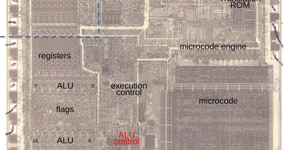
The ALU is the mathematical heart of the processor, handling everything from simple addition to complex BCD (Binary Coded Decimal) adjustments. But the ALU itself is just a dumb calculator; it needs a conductor to tell it what to do. That conductor is the ALU control logic, a fascinating block of silicon that acts as the translator between the microcode ROM and the ALU's execution gates.
The Two-Step Dance of Microcode
Unlike a simple fetch-and-execute cycle, the 8086 relies heavily on microcode. Most machine instructions are actually programs stored in a hidden ROM, consisting of a series of micro-instructions. The 8086 uses a unique architecture where each micro-instruction performs two unrelated tasks simultaneously: moving data and performing a secondary operation (like an ALU calc or a jump).
However, there is a latency quirk. The 8086 requires a specific micro-instruction to configure the ALU, but the result of that calculation isn't available until a later micro-instruction moves it to a destination. This creates a state-holding problem: the hardware must remember what operation it was asked to perform between clock cycles.
To handle this, the control logic uses flip-flops to latch the operation code. Furthermore, many machine instructions (ADD, SUB, ADC, SBB, AND, OR, XOR, CMP) share the exact same microcode. The micro-instruction doesn't specify the operation directly; instead, it uses a placeholder called "XI" (Execute Instruction). The hardware then intercepts this placeholder and substitutes the real operation based on bits from the machine instruction opcode.
The ALU Circuit: Lookup Tables on Silicon
The 8086 ALU itself is a masterpiece of gate optimization. While some processors use separate circuits for every operation, the 8086 uses a system of lookup tables (LUTs) embedded in the silicon. For every bit of the 16-bit ALU, there is a circuit that takes six control signals to determine carry generation and propagation.
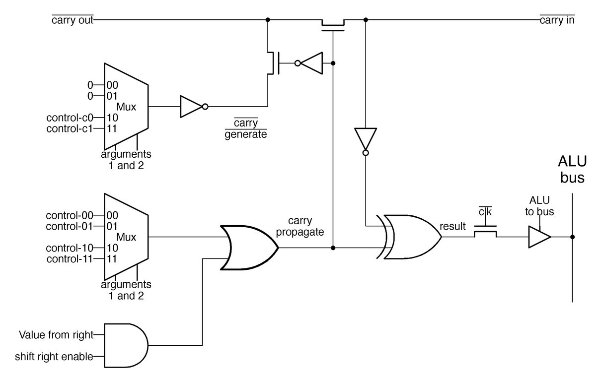
By feeding the correct pattern of signals into these LUTs, the ALU reconfigures itself on the fly. One set of signals makes it an adder; another set makes it a logic XOR unit. This allows the 8086 to support 28 different operations without needing 28 separate physical circuits.
The Control Logic: PLAs and Drivers
The bridge between the microcode and the ALU LUTs is the ALU control logic, visible on the die as a distinct strip at the bottom of the chip.
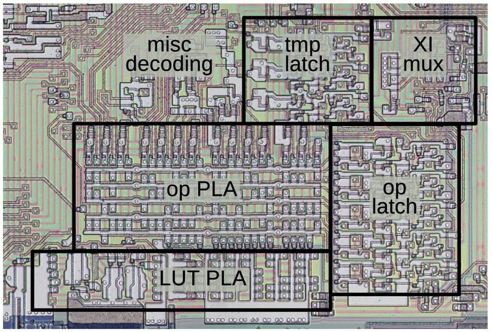
This section of the die (shown above with the metal layer removed) contains several key components:
- The XI Multiplexer: This block handles the substitution of the "XI" opcode. It grabs bits from the "X" register (which holds bits 5-3 of the machine instruction), the instruction register, and the Group Decode ROM to construct the actual 5-bit ALU operation field.
- Programmable Logic Arrays (PLAs): The control logic relies heavily on PLAs to decode the 5-bit operation field into the 27 specific control signals needed by the ALU. One PLA generates signals for special cases (like incrementing by 2 or BCD adjustments), while a second PLA generates the six critical signals for the LUTs.
The Bootstrap Driver: Boosting Performance
One of the most interesting electrical challenges in this section is driving the ALU gates. The 8086 uses NMOS technology, which is notoriously bad at pulling signals high (passing a "1"). A standard NMOS output might only reach 4.5V, causing a voltage drop that slows down transistor switching.
To solve this, the control logic uses a dynamic circuit known as a Bootstrap Wordline Driver.
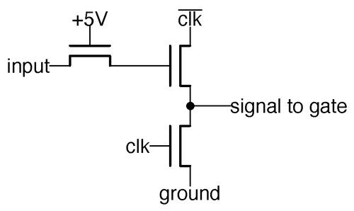
This circuit uses capacitance to boost the gate voltage of the output transistor above the supply voltage. When the clock signal toggles, the capacitance in the driver pulls the gate voltage even higher, ensuring the output transistor turns on fully. This delivers a full-voltage signal to the ALU gates, overcoming the threshold voltage drop and ensuring the ALU switches as fast as possible. It’s a clever hack that squeezes performance out of the limitations of the manufacturing process.
Conclusion: The Cost of Complexity
Examining the 8086's ALU control logic highlights the stark difference between RISC and CISC philosophies. A RISC processor has simple, direct decoding. The 8086, however, is a web of multiplexers, latches, and PLAs designed to handle the massive variety of instruction formats and addressing modes.
Whether it's handling the inversion of the carry flag for subtraction, managing the four types of BCD adjustments, or remembering the ALU operation across micro-instruction boundaries, this control block proves that the x86 architecture's longevity is built on a foundation of incredibly complex, yet highly optimized, silicon.
For a deeper look at the microcode analysis referenced here, check out Andrew Jenner's 8086 microcode disassembly.
Comments
Please log in or register to join the discussion