A detailed walk‑through of lcamtuf’s second‑generation volt‑meter clock, covering design, CNC milling, wood bending, and the minimalist AVR‑based drive circuit that powers the analog gauges.
A Nicer Voltmeter Clock – How I Refined the Design
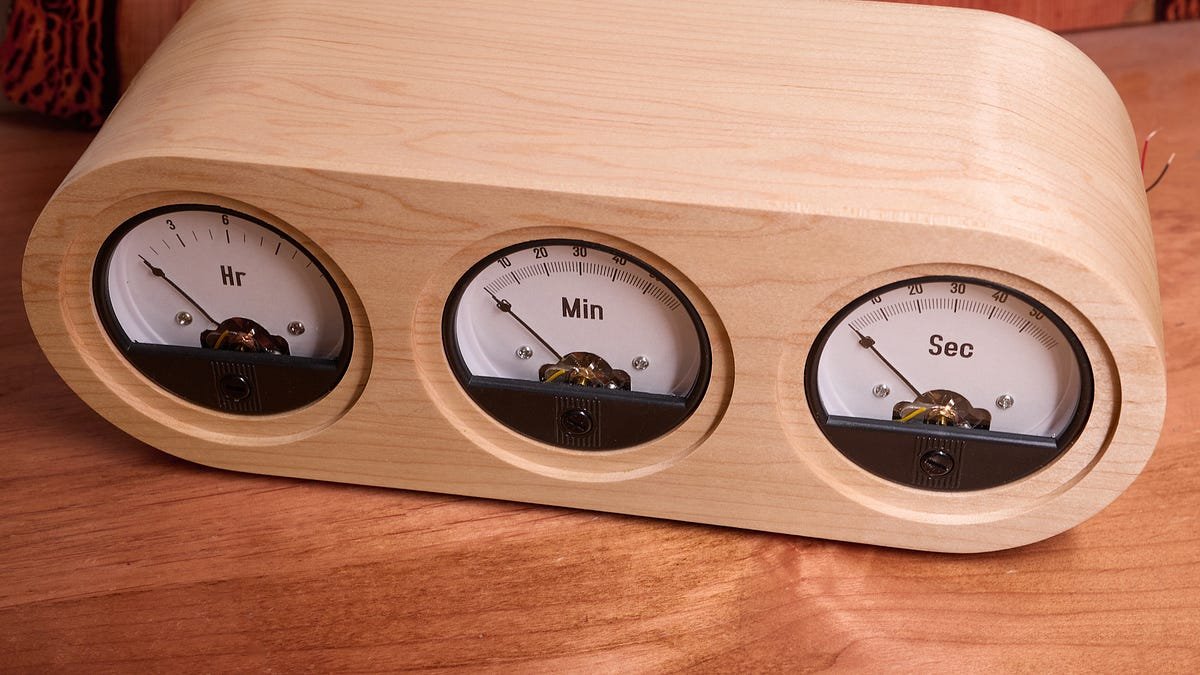
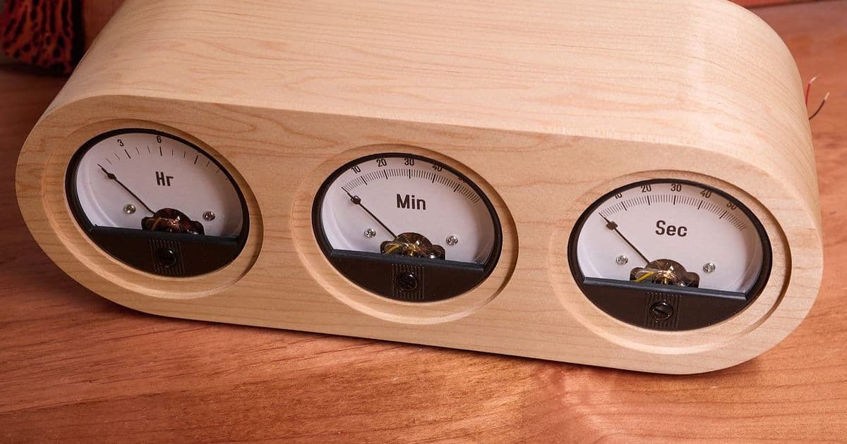
When I first cobbled together a voltmeter‑clock back in 2019, the result was functional but a bit rough around the edges. The concept – using three 90° panel voltmeters as hour, minute and second hands – is simple, yet the execution can quickly become a maze of complicated gear trains, custom PCBs, and ugly enclosures. After a few years of watching the internet crowd around over‑engineered versions, I decided to revisit the project with a focus on clean aesthetics, easy construction, and minimal parts. Below is the full story, from the initial 3‑D mockup to the final AVR‑driven circuit.
1. From Sketch to CNC‑Milled Parts
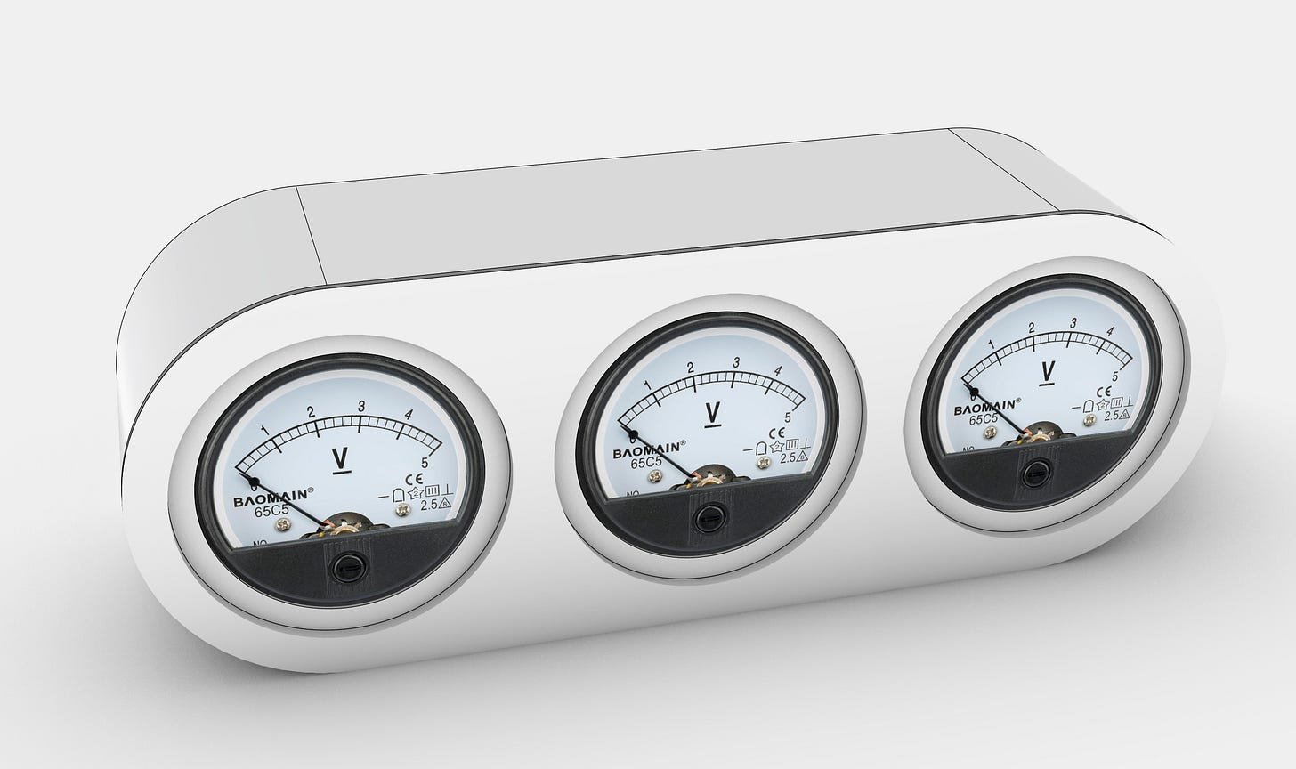
The first step was to visualise the new clock in a CAD environment. I chose Rhino 3D because its NURBS modeling makes it easy to lay out the curved side wall and the recessed front panel.
Why CNC?
- Precision – The panel voltmeters have a tight tolerance on the face dimensions; a CNC‑milled pocket guarantees the decals line up perfectly.
- Repeatability – Once the toolpaths are saved, anyone can reproduce the parts without hand‑routing.
- Speed – What used to take a full day of hand‑cutting was reduced to a couple of hours on a 3‑axis router.
The front and back plates were milled from 6 mm Baltic birch plywood. The side wall, a single 12 mm thick strip, needed a gentle 30° curve. Rather than building a steam‑bending jig, I cut a series of internal relief notches (about 2 mm deep) along the inner edge. This lets the wood flex like a spring, making the bend achievable with just a wooden template and a few clamps.
Practical Tip
If you don’t have a CNC router, a high‑quality handheld router with a guide rail can produce the same pockets. Just take your time on the notches – the more evenly spaced they are, the smoother the final curve.
2. Panel Meter Preparation
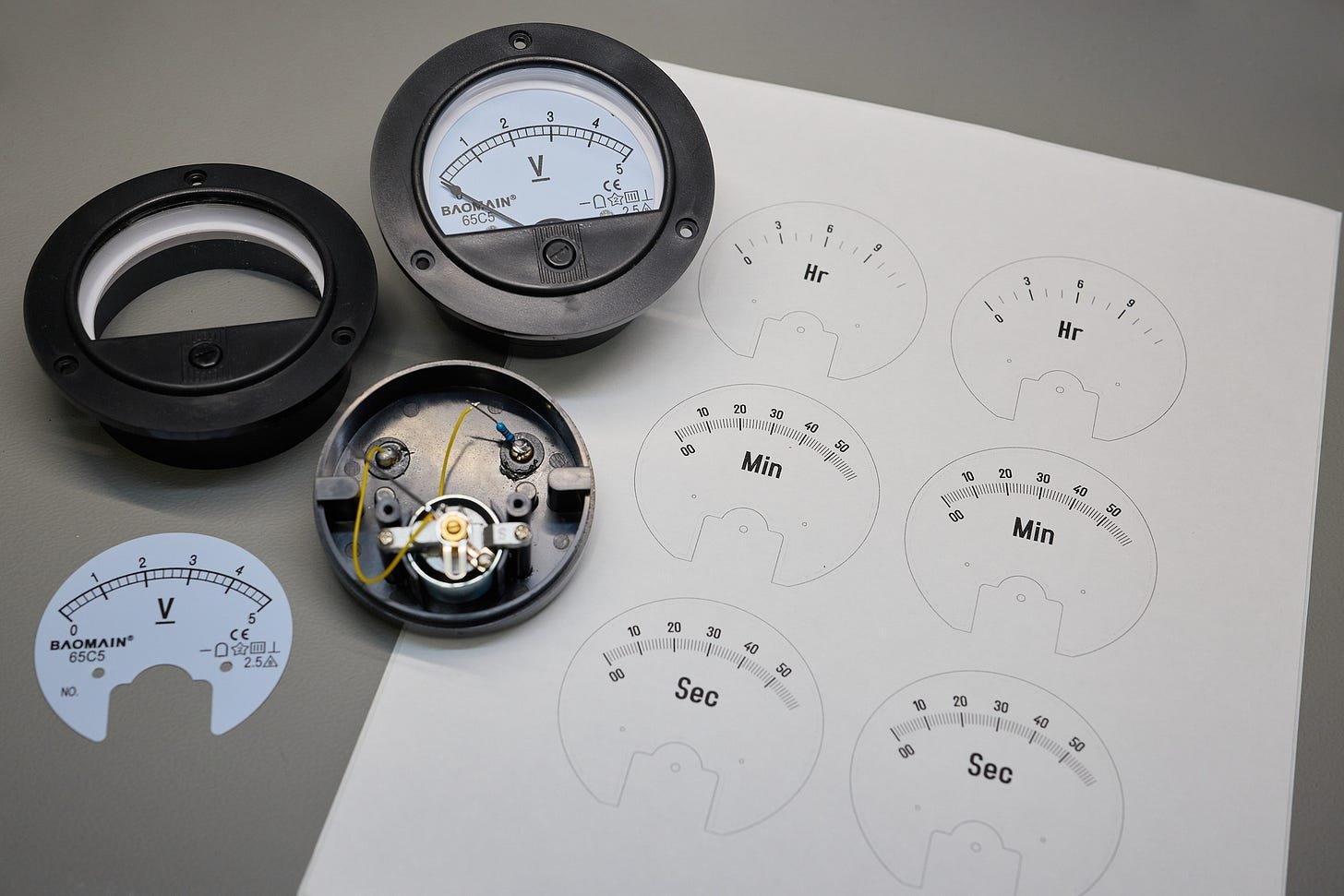
I sourced three generic 90° panel voltmeters from Amazon (≈ $9 each). The cheap “Baomain 65C5” units have a bulky plastic flange that spoils the visual line. To hide it, I:
- Disassembled each meter and measured the face dimensions with a digital caliper.
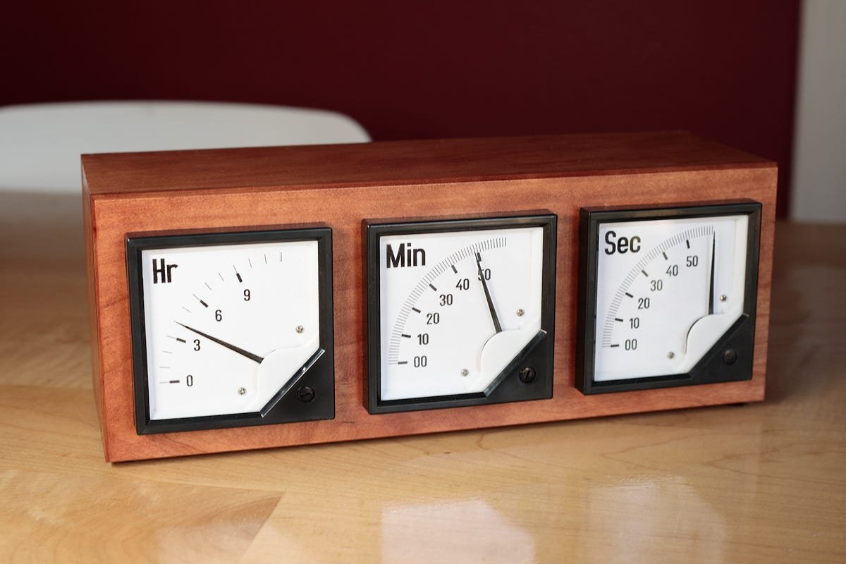
- Designed printable PDF templates for the hour, minute and second scales. The hour dial uses 13 divisions (0‑12) while the minute/second dials have 61 divisions (00‑60) to allow continuous motion.
- Printed the templates on adhesive paper and applied them with a rubber squeegee to avoid bubbles.
All templates are available in the GitHub repository.
Practical Tip
When applying the decals, work from the center outward. This reduces the chance of trapped air and ensures the printed numbers stay crisp.
3. Wood Bending Without Steam
The curved side wall is the visual centerpiece. Here’s how I did it without a steam‑bending rig:
- Moisten the plywood lightly with a spray bottle – just enough to make the fibers pliable.
- Clamp the notched strip onto a pre‑shaped wooden template that matches the desired radius.
- Leave it to dry for 48 hours. As the wood dries, it retains the curvature.
- Glue the curved side wall to the front and back plates using a second template (cut from scrap plywood) to keep the joints flush.
The result is a seamless, rounded envelope that hides the meter flanges and gives the clock a modern, sculptural look.
4. Minimalist Drive Circuit – AVR128DB28
The electronics are intentionally simple. The entire clock runs on a single AVR128DB28 MCU, powered from a 5 V wall wart. Key components:
- 8 MHz crystal (ECS‑80‑18‑4X‑CKM) – provides a stable time base. A 32.768 kHz crystal would also work if you prefer lower power.
- Two push‑buttons on the back (PD6, PD7) for hour/minute set.
- Three digital output pins (PC0‑PC2) directly drive the panel meters.
How the Meter Drive Works
Instead of a DAC, the MCU generates a high‑frequency pulse train (≈ 10 kHz). By adjusting the duty cycle, the average voltage seen by the meter’s moving coil changes, and the needle settles at the corresponding position. The meter’s mechanical inertia smooths out the rapid toggling, giving the appearance of a continuously moving hand.
The firmware lives in a compact, well‑commented repository:
- Clock firmware on GitHub
- The main loop calculates the required duty cycle for each gauge based on the current time, then toggles the pins manually. Using the built‑in PWM module would add complexity without measurable benefit for a 10 Hz update rate.
Practical Advice for Builders
- Measure the meter’s coil resistance (typically 20‑30 Ω). If you notice sluggish needle movement, increase the pulse frequency slightly.
- Add a 0.1 µF decoupling capacitor across the supply pins of the MCU to smooth out the current spikes caused by the rapid toggling.
- Test the duty‑cycle range on a bench power supply before soldering – you’ll see the needle sweep from 0 % to 100 % duty.
5. Assembly & Finishing Touches
- Solder the MCU, crystal, and button matrix onto a small protoboard. Keep the wiring short to reduce noise.
- Mount the three meters into the milled pockets, secure the decals, and connect the output pins.
- Apply a coat of nitrocellulose lacquer to the wood for a smooth, durable finish.
- Calibrate the clock by holding the set buttons while the firmware runs a short calibration routine (see
calibrate.cin the repo).
The final product sits on a desk with a clean, modern silhouette, while the analog meters give a nostalgic nod to classic instrumentation.
6. Takeaways for the Maker Community
- Simplicity wins – A single MCU and a pulse‑width technique replace costly DACs and motor drivers.
- CNC + wood bending – Combining digital fabrication with traditional woodworking yields high‑quality enclosures without expensive jigs.
- Open‑source resources – All design files, PCB schematics, and firmware are freely available, so you can adapt the clock to other gauge types or add features like Bluetooth time sync.
If you decide to build your own version, feel free to open an issue on the GitHub page – I’m happy to help troubleshoot the wood bend or the duty‑cycle calibration.
Happy building, and may your hands always point to the right time!
Comments
Please log in or register to join the discussion