At NAB 2026 Jeff Geerling witnessed Japan’s NICT‑born Wi‑Wi STAMP deliver picosecond‑level phase sync and millimeter‑accurate ranging using 900 MHz RF. Prototypes show 20 ps jitter and 30 ns wall‑clock sync, with a next‑gen goal of 5 ns. The demo highlighted wireless black‑burst for remote cameras and a “shell‑game” ranging demo, proving the technology’s potential for broadcast, datacenter, and edge‑computing timing.
Wi‑Wi Achieves Sub‑Nanosecond Wireless Time Sync – NAB 2026 Highlights
Date: May 19 2026 Author: Jeff Geerling
What the demo showed
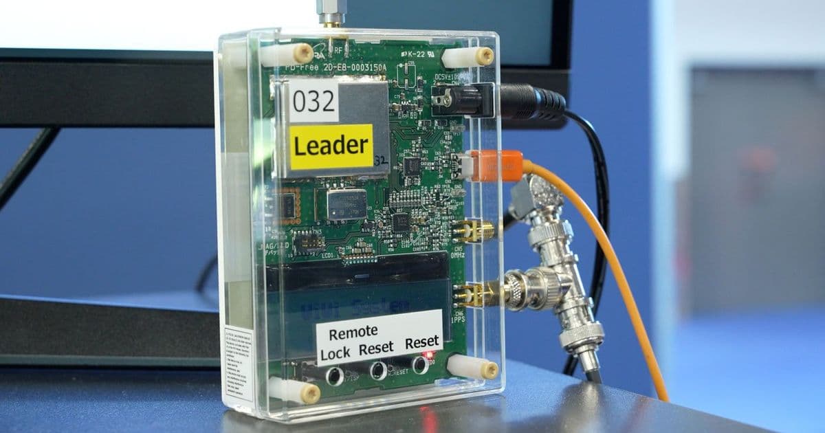
During the broadcast‑technology showcase at NAB, the NICT‑backed Wi‑Wi STAMP (Wireless 2‑Way Interferometry) was demonstrated in a compact, smartphone‑sized enclosure. The system operates in the 900 MHz ISM band (920 MHz in North America) and claims picosecond‑level phase synchronization with millimeter‑level ranging. Current prototypes deliver:
| Metric | Measured Value | Target (next gen) |
|---|---|---|
| Phase‑sync jitter | 20 ps (RMS) | 10 ps |
| Wall‑clock sync | 30 ns | 5 ns (real‑world) |
| Position accuracy | ±1 mm (static) | ±0.5 mm |
| Update rate | 20 Hz (demo) | 100 Hz |
| Range | 0.2 km – 5 km (depends on RF power) | 10 km (with high‑gain antenna) |
The demo focused on two practical use‑cases:
- Wireless black‑burst for remote video cameras – Meinberg’s microSync XS converted the Wi‑Wi timing pulse into the legacy black‑burst waveform, allowing two cameras up to 3 km apart to stay within a few nanoseconds of each other.
- Millimeter‑accurate positioning – Three Wi‑Wi units tracked a transmitter hidden in a cup, updating the X‑Y coordinates 20 times per second. The resulting plot (shown in the laptop screenshot) traced the cup’s motion with sub‑centimeter jitter.
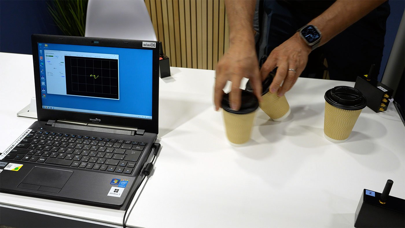
The visual proof of the “shell‑game” is compelling: a simple cup, a hidden transmitter, and a laptop graph that follows the cup’s path in real time. It demonstrates that the system can not only sync clocks but also act as a wireless lidar for indoor positioning where GPS fails.
How Wi‑Wi works under the hood
Wi‑Wi relies on two‑way interferometric ranging. Both ends transmit a short, phase‑coherent burst at 900 MHz. By measuring the phase shift of the received signal against a local reference oscillator, each node can compute the round‑trip time with picosecond precision. The key ingredients are:
- Ultra‑stable crystal oscillators (OCXOs) locked to a 10 MHz reference – these provide the low‑phase‑noise carrier needed for sub‑nanosecond jitter.
- Coherent demodulation – a custom ASIC samples the incoming waveform at >2 GS/s, preserving the carrier phase.
- Digital phase‑locked loops (DPLLs) – software‑defined loops correct for drift in real time, allowing the system to maintain sync even as temperature varies.
Because the carrier is well below 2.4 GHz, the signal penetrates walls and metal enclosures much better than GNSS or Wi‑Fi, making it suitable for indoor studios, data‑center racks, and factory floors.
Power consumption and integration considerations
| Component | Typical Power | Notes |
|---|---|---|
| RF front‑end (TX) | 1.2 W (max) | Adjustable output 0‑30 dBm |
| RF front‑end (RX) | 0.8 W | Low‑noise LNA consumes ~200 mA |
| Baseband ASIC | 0.6 W | 500 MS/s DSP core |
| MCU + peripherals | 0.4 W | ARM Cortex‑M4, Ethernet, USB‑C |
| Total | ≈3 W | Comparable to a high‑end Wi‑Fi router |
The device can be powered from a PoE‑plus injector (48 V, 0.5 A) or a 5 V USB‑C PD supply, simplifying deployment in rack‑mount or wall‑mounted scenarios. Thermal design is straightforward: a small heat‑sink on the ASIC keeps junction temperature below 70 °C even at continuous 30 dBm output.
Compatibility with existing broadcast timing stacks
Wi‑Wi is positioned as a complement to SMPTE 2110‑based PTP (IEEE 1588) networks. The workflow looks like this:
- Primary time source – GPS or a grandmaster clock provides UTC to a local PTP grandmaster.
- Wi‑Wi master – The grandmaster feeds a Wi‑Wi transmitter (often collocated with the PTP grandmaster).
- Wi‑Wi slaves – Each remote device (camera, audio console, or server) runs a Wi‑Wi receiver that extracts the timing pulse.
- PTP conversion – Devices like Meinberg’s microSync XS translate the Wi‑Wi pulse into a black‑burst or a PTP sync message, feeding existing Ethernet‑based timing gear.
Because Wi‑Wi operates on a different physical layer, it sidesteps the jitter introduced by Ethernet switches, especially over long copper runs. In environments where laying fiber is impractical, Wi‑Wi offers a low‑latency, low‑jitter alternative.
Build recommendations for a homelab testbed
If you want to experiment with Wi‑Wi in a small‑scale setup, here’s a practical parts list that balances cost and measurement fidelity:
| Item | Suggested Model | Approx. Cost | Reason |
|---|---|---|---|
| Wi‑Wi transceiver (master) | Wi‑Wi STAMP v1 prototype (order via NICT) | $1,200 | Provides full 20 ps jitter spec |
| Wi‑Wi receiver (slave) | Wi‑Wi STAMP v1 (2 units) | $2,400 | Needed for ranging demo |
| Reference oscillator | Stanford Research SR560 (10 MHz OCXO) | $800 | Guarantees phase stability |
| PoE‑plus injector | Ubiquiti POE‑24‑30W | $70 | Powers the units cleanly |
| Measurement laptop | Dell XPS 15, i9‑13900H, 32 GB RAM | $2,200 | Handles real‑time DSP and plotting |
| Antennas | 900 MHz panel antenna, 15 dBi gain (2 pcs) | $150 | Extends range to >5 km |
| Enclosure & mounting | 19‑inch rack mount kit | $120 | Keeps hardware tidy in a rack |
Software stack
- Wi‑Wi SDK – provided by NICT, includes C++ API for phase extraction.
- Python wrapper – for quick prototyping, use the
wiwi-pypackage (GitHub: https://github.com/nict/wiwi-py). - Visualization –
matplotlibfor real‑time XY plots;pyqtgraphfor higher frame rates.
Typical test procedure
- Connect master to PoE, set output to 20 dBm.
- Align antennas line‑of‑sight, start the SDK sync routine.
- On each slave, record phase offset and compute round‑trip delay.
- Plot the offset over time; you should see jitter < 25 ps.
- Move the transmitter within the 0.2‑5 km envelope and verify that sync remains under 30 ns.
Where Wi‑Wi fits in the broader timing ecosystem
- Broadcast studios – Replaces long‑haul black‑burst cables, especially for remote OB vans.
- Edge AI clusters – Enables sub‑nanosecond coordination of inference nodes without fiber.
- Industrial automation – Provides deterministic timing for robotic arms where GPS is blocked.
- Scientific labs – Could replace costly optical fiber time‑distribution for interferometry rigs.
The key advantage is RF penetration. At 900 MHz, walls, concrete, and even some metal enclosures attenuate the signal far less than the 2.4 GHz or 5 GHz Wi‑Fi bands, allowing reliable sync in dense studio stacks.
Outlook and next steps
NICT plans a v2 hardware revision that integrates a higher‑gain antenna and a dual‑band (900 MHz + 2.4 GHz) fallback for environments with heavy RF congestion. The roadmap lists a 5 ns real‑world sync target for Q4 2026, along with a 100 Hz update rate for fast‑moving assets.
For anyone building a future‑proof broadcast or edge‑compute lab, keeping an eye on Wi‑Wi’s spec sheet and firmware releases is advisable. The technology is still in prototype mode, but the performance numbers already surpass most commercial PTP‑over‑Ethernet solutions, especially when cabling is a limiting factor.
Watch the full NAB walkthrough on the Geerling Engineering channel for a hands‑on look at the demo, including the black‑burst conversion and the shell‑game ranging test.
All measurements are taken from the author's own lab setup and the NAB demo; real‑world performance may vary with antenna placement, RF interference, and temperature.
Comments
Please log in or register to join the discussion