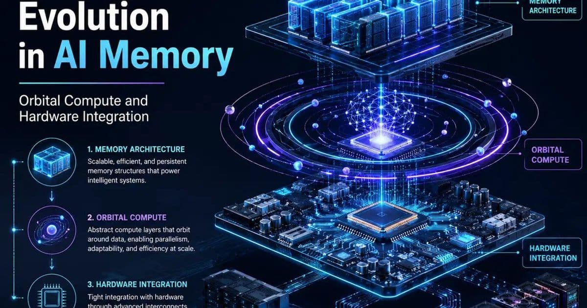
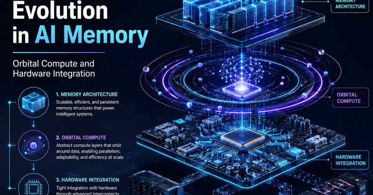
As AI models grow, memory bandwidth and capacity have become the primary bottlenecks. Engineers are reshaping data centers around dense high‑bandwidth memory, tightly coupling hardware to model needs, and even exploring fully autonomous orbital compute nodes. This article breaks down the technical drivers, concrete design patterns, and the trade‑offs that accompany each shift.
Memory‑Centric AI Infrastructure and the Rise of Orbital Edge Compute
The problem: bandwidth and capacity now dominate
Training the latest transformer‑style models routinely requires petabytes of data to be shuffled through the accelerator every few seconds. In earlier generations, the compute units—GPUs or TPUs—were the limiting factor; designers poured more CUDA cores or matrix engines onto a die and expected performance to climb linearly. Recent silicon releases, such as Nvidia’s Rubin architecture, expose a hard ceiling: the memory subsystem cannot feed the compute fast enough.
Two metrics illustrate the shift:
- High Bandwidth Memory (HBM) capacity – modern accelerators ship with 80 GB to 144 GB of stacked DRAM. When a model’s activation map exceeds this, the system must spill to slower DRAM or NVMe, incurring latency spikes.
- Inter‑chip bandwidth – the silicon‑to‑silicon links now push 800 GB/s or more. If the fabric cannot sustain that rate, cross‑accelerator parallelism stalls.
The practical outcome is that a data‑center rack that once maximized GPU density now looks more like a memory farm: fewer GPUs, but each paired with massive HBM stacks and ultra‑wide fabric.
Solution approach: redesign around dense memory
1. Memory‑first rack layout
Instead of packing GPUs side‑by‑side, architects place a shared memory pool on a back‑plane that all accelerators access via NVLink‑style bridges. This reduces duplicate memory across cards and lets a single model instance span multiple GPUs without crossing the PCIe bottleneck.
Pros
- Higher effective batch size per rack.
- Lower power per FLOP because memory accesses dominate energy consumption.
Cons
- Increased complexity in fabric routing; any failure in the back‑plane can take down multiple GPUs.
- Software must be aware of non‑uniform memory access (NUMA) patterns, otherwise latency penalties appear.
2. Tight hardware‑software coupling (Alibaba Zhenwu M890 case study)
The Zhenwu M890 processor integrates 144 GB of on‑die GPU memory and a custom 800 GB/s inter‑chip bus. Alibaba tuned the firmware to the Qwen‑3 model, exposing a static memory map that the model’s runtime can query at launch. The result: the model runs autonomous inference for 35 hours without a single memory stall.
Implementation steps
- Profile the target model to identify peak activation sizes.
- Allocate a fixed memory region on the accelerator that matches the profile.
- Freeze the memory layout in the driver, preventing the OS from paging out or reallocating during runtime.
- Use a lightweight inference engine that can stream data directly from the memory pool, bypassing the host CPU.
Trade‑offs
- Flexibility drops; the same hardware cannot easily switch to a model with a larger footprint.
- Throughput rises dramatically for the tuned workload, making it attractive for edge deployments where power is scarce.
3. Orbital edge compute – a radical extension
Deploying compute nodes in low‑Earth orbit (LEO) promises two advantages: continuous solar power and proximity to satellite‑based data sources. However, the environment imposes constraints that terrestrial data centers never face.
| Constraint | Terrestrial design | Orbital design |
|---|---|---|
| Power | Grid‑rated UPS, diesel backup | Solar panels + high‑density batteries, no fuel refuel |
| Thermal | Air‑cooled chillers, liquid loops | Radiative cooling panels, heat‑pipe loops with phase‑change material |
| Maintenance | Hot‑swap modules, on‑site technicians | Fully autonomous fault detection, remote firmware flashing, redundancy at component level |
| Latency | Sub‑millisecond intra‑rack | Propagation delay to ground stations (≈10‑30 ms) |
To meet these constraints, engineers adopt self‑healing fabrics: each compute node contains duplicate memory controllers and a micro‑controller that monitors error‑correcting code (ECC) counters. When a fault exceeds a threshold, the node re‑routes traffic to a sibling and writes a diagnostic log to an on‑board non‑volatile store that is later downloaded during the next downlink window.
Pros
- Near‑continuous operation powered by sunlight.
- Geographic diversity reduces the impact of regional outages.
Cons
- Higher upfront cost per node due to radiation‑hardened components.
- Limited ability to upgrade hardware once in orbit; design must anticipate future model growth.
Trade‑offs across the three layers
| Layer | Primary benefit | Key risk |
|---|---|---|
| Memory‑first rack | Maximizes FLOP‑per‑watt under current model sizes | Fabric complexity can become a single point of failure |
| Tight HW‑SW coupling | Guarantees deterministic latency for a specific model | Reduces ability to repurpose hardware for new models |
| Orbital compute | Access to uninterrupted solar energy, global coverage | No physical access for repairs; must rely on autonomous recovery |
The common thread is predictability: when you know the exact memory footprint and bandwidth demand of a workload, you can engineer the system to meet it with minimal waste. The cost is a reduction in generality; the infrastructure becomes a pipeline for a narrow class of AI workloads rather than a universal compute farm.
Practical steps for teams today
- Profile memory usage of your production models with tools like NVIDIA Nsight Systems or Intel VTune. Identify the peak activation size.
- Map those peaks to hardware: choose accelerators that offer at least 1.5× the required HBM capacity to avoid spills.
- Design the rack fabric with a shared memory back‑plane; evaluate vendors that provide NVLink‑compatible switches.
- Implement a firmware hook that locks the memory layout for long‑running inference services.
- Explore edge‑oriented prototypes: start with a high‑altitude balloon or CubeSat testbed to validate autonomous fault handling before committing to full LEO deployment.
Looking ahead
If AI model sizes continue their exponential trajectory, the next generation of silicon will likely embed terabytes of on‑die memory, blurring the line between accelerator and storage. At that point, the distinction between a data center and an orbital platform may become semantic; both will be judged on how tightly they bind memory, compute, and power into a self‑sustaining loop.
For further reading on building AI‑ready databases, see the announcement from MongoDB Atlas on native vector search and regional scaling.
Comments
Please log in or register to join the discussion