A detailed account of repairing two broken Agilent 54831 oscilloscopes from the early 2000s, involving PC hardware troubleshooting, hard drive replacement, software installation, and a bandwidth upgrade modification.
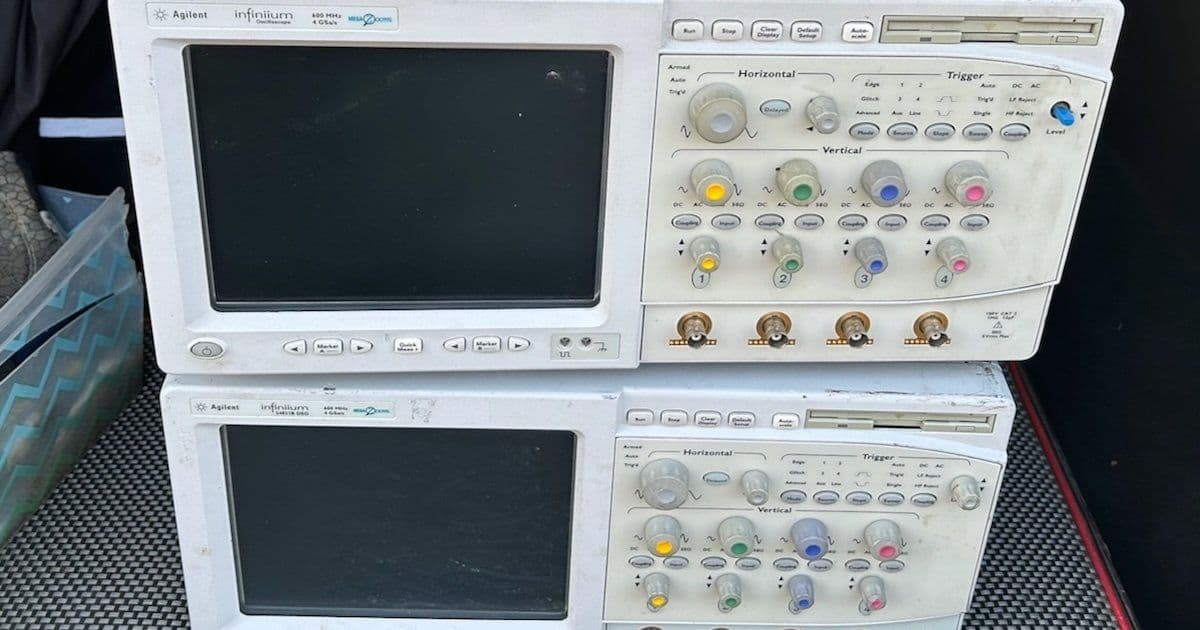
After six months of deprivation, the Silicon Valley Electronics Flea Market season returned, and I found myself face-to-face with a vendor selling not one but two broken Agilent 54831 oscilloscopes for $200. Despite the marital implications of adding two more "boat anchors" to my garage, I made the courageous decision to take the deal, especially since others were already lining up behind me.
The Agilent 54831: A Windows-Based Vintage Scope
The Agilent 54831 represents an interesting era in test equipment history. Introduced in 2002, it was one of the first oscilloscopes to use Windows as its base operating system. The specs remain respectable by today's hobbyist standards: 4 channels, 600 MHz bandwidth, and 4 Gsps sampling rate. However, there are some limitations - channels 1 and 2 share the same ADC with channels 3 and 4, and to achieve the full 4 Gsps rate, you can only use one channel from each pair.
The scope's slightly more potent sibling, the 54832, offers 1 GHz bandwidth, but like the Tektronix TDS 754D and TDS 784D, the 54831 can be upgraded to a 54832 with a single resistor modification. This HP 548xx series was groundbreaking for its time, with early versions running Windows 98 SE Embedded and later versions switching to Windows XP.
Inside the PC System
Opening up the 54831 reveals what's essentially a PC with custom PCI plug-in boards. The design uses separate top and bottom covers, requiring removal of 16 screws just for the top cover. Inside, you'll find:
- A Motorola VP22 motherboard with Pentium III 1 GHz CPU
- PCI to PCI bridge board for the acquisition board
- GPIB interface board
- Display adapter based on CHIPS F65550 (handling both VGA and LCD interfaces)
- Waveform overlay rendering board with Altera FPGA
- Standard PC components including CDROM drive, Superdisk LS120 floppy drive, and 10 GB IBM TravelStar hard drive
The display system is particularly interesting - similar to some 1990s 3D graphics accelerators, the VGA card renders the GUI while waveforms are rendered by a separate card and merged with the GUI in hardware.
Unit A: The Military Version
Unit A, marked as the "M" military version, was assembled in Singapore rather than Malaysia. The seller claimed it didn't work at all, and he was correct - plugging in the power cord immediately produced long, ominous beeps with no further activity.
My first suspect was the IBM TravelStar hard drive, notorious for failures with stuck read/write head assemblies. After disassembling the entire PC section of the scope (disconnecting all cables, removing PCI boards, CDROM drive, and DRAM stick), I extracted the hard drive only to discover it worked fine when connected to a PC via USB to SATA adapter. Using HDD Raw Copy Tool, I created a backup image without any errors.
With the drive confirmed functional, I focused on getting the PC to boot. Stripping the motherboard of all custom cards and attempting to boot with just DRAM and an old PCI VGA card didn't work either. The error signature was a repeating pattern of a long beep followed by a long pause, which didn't match any standard AMI BIOS error codes.
Suspecting the CPU might be the issue, I removed the Thermaltake Golden Orb Mini cooler (requiring a clockwise rotation to detach) and reseated the CPU. To my surprise, this simple action fixed the problem. After reinstalling all the PCI boards and cables, the scope finally booted successfully.
Unit B: The Windows XP Version
Unit B, a slightly younger B version made in Malaysia, presented a different challenge. It would light up but get stuck at the boot screen, with the BIOS not detecting any drives. Opening it up revealed why - there were no drives at all, no IDE cables, and the custom board with the LS120 floppy drive connector was missing.
I decided to replace the missing storage with a CompactFlash adapter that plugs straight into the motherboard. For around $8, I found an adapter board that accepts a 4-pin Molex floppy connector for 5V or 3V supply. I also purchased 40-pin flat cables for $9 to connect both the CF card and a CDROM drive.
Installing the Software
The software installation proved to be the most challenging part. While finding the software wasn't difficult - the scope is popular among hobbyists who share resources - determining which version to use was tricky. I ultimately used an image from Tony_G's OneDrive, specifically the 6.38 GB xp54831.vhdx file in the 54831M directory.
The installation process involved:
- Installing Rufus to create bootable USB drives
- Connecting the CompactFlash card to a PC with a CF to USB adapter
- Copying xp54831.vhdx to the CF card using Rufus
- Installing the CF card into the scope and booting
The image contained a Symantec Ghost sub-image that needed to be run after booting. Following the installation instructions in Install hints.pdf eventually led to a working system, though initially plagued by noise on the signals.
Calibration and Performance
The noise issue was resolved through calibration - running the calibration routine in the menu for about an hour eliminated the artifacts. After calibration, the scope performed excellently.
CPU Temperature Management
After extended use, the scope began emitting a persistent CPU temperature alarm. Rather than replacing capacitors on the motherboard or main power supply, I opted to disable the CPU temperature alarm in the BIOS PC Health Status section. Monitoring temperatures with Core Temp after applying thermal paste and reseating the cooler showed temperatures around 40C at rest and never exceeding 65C under full load, well within the Pentium III's 75C maximum junction temperature specification.
The 1 GHz Bandwidth Upgrade
The final modification was the resistor upgrade to achieve 1 GHz bandwidth. Located on the acquisition board, removing a single resistor changed the scope's identification from Agilent 54831B to Agilent 54832B. Testing with the AUX Out signal showed the rise time improving from 481 ps to 331 ps, corresponding to a bandwidth increase from 727 MHz to 1057 MHz - within spec and confirming the modification worked.
Conclusion
For $200 and approximately $30 in additional components, I acquired two working 4 Gsps scopes with either 600 MHz or 1 GHz bandwidth. I sold Unit A for $200, which I believe was an excellent deal for the buyer, and kept the other unit. The project demonstrated that with patience, basic PC hardware knowledge, and access to shared resources from the hobbyist community, it's possible to resurrect and even enhance vintage test equipment that would otherwise be discarded.
The entire experience highlighted how test equipment from the early 2000s represents a fascinating intersection of traditional instrumentation and PC technology, with Windows-based systems, standard PC components, and custom hardware working together to create powerful measurement tools that remain useful decades later.
Comments
Please log in or register to join the discussion